
Building roads with EasyRoads3D is a straight forward process. A new road object is created through the 2nd tab from the left in the Inspector. The road shape is defined by adding markers using Shift + Click in Scene View. The road will become visible after adding two markers. After that you can continue and make changes. Add more markers, move markers to fine tune the shape, insert markers (the I key) or remove selected markers (the R key).
There are however a number of tools and options available to fine tune the road shape, customize the road shape, make the road look less computer generated and get better results in shorter time. These options will be discussed in this section.
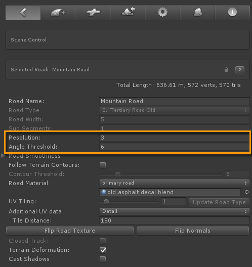
"Resolution" controls the geometry of the road. It represents the distance between vertices. So contrary to modelling apps an higher resolution value means less triangles,
"Angle Threshold" can be used to reduce triangle count with minimal loss of quality or add more detail in curves. Use lower threshold values together with higher resolution values.
One thing to take into consideration with higher resolution values and Angle thresholds is that the road geomtery becomes irregular. This can have an undesired effect on specific side objects that are set to clamp to the road geometry. These type of side objects may not look as expected. You may want to try a lower fixed "Resolution" value in that case.
The default control type is "Spline Controller". This generally works well especially for long winding roads. It will create the road shape between two markers using the previous and next markers as control points. This results in a smooth spline shape. You probably want to avoid large differences in distances between the involved markers as this will have an impact on the curve strength. generally it is good practise to position markers at more or less similar distances.
Sometimes however you want more control over the road shape. This can be achieved with the other control types, the"Circular" and "Straight" options.
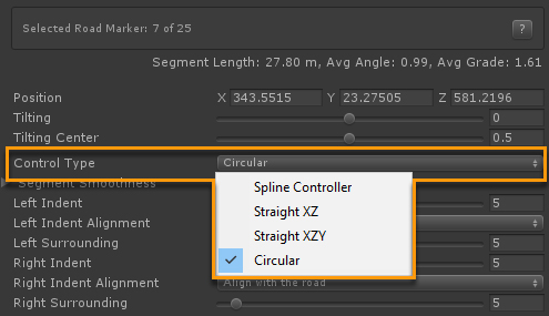
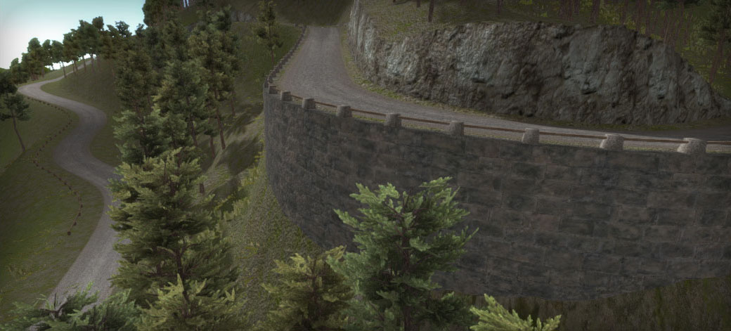
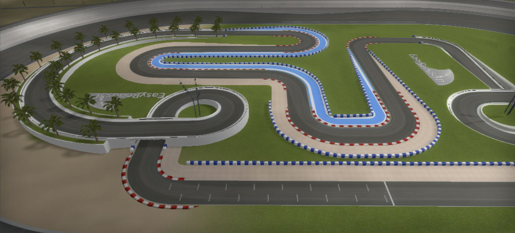
The Circular control type is useful for race tracks and hairpins like in the first mountain road image (marker 32).
Straight segments are also typically for race tracks but can also be useful for winding roads when segments are too curvy. Inserting a straight segment between two spline based segments can level this out. The XYZ version will result in a perfect straight line, while the "XZ" variation will preserve the smooth spline shape on the Y coordinate.
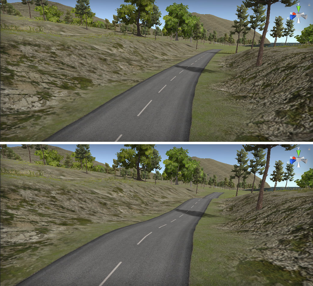
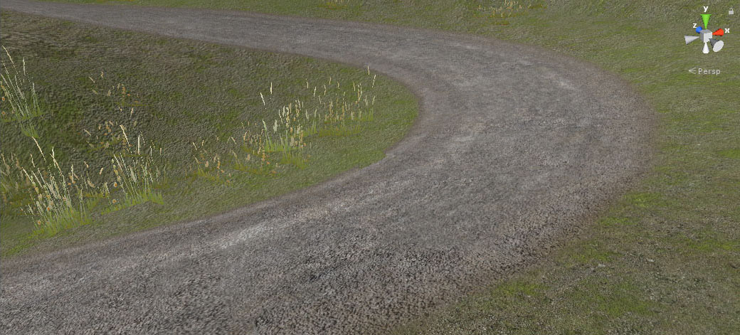
By default the roads are generated exactly according the marker position and the marker controller types discussed above, the top image.
"Follow Terrain Contours" (in the Inspector of the selected road) is a poweful tool. The road will adjust to the terrain shape resulting in a more realistic look without having to add additional markers. The second image above uses "Follow Terrain Contours".
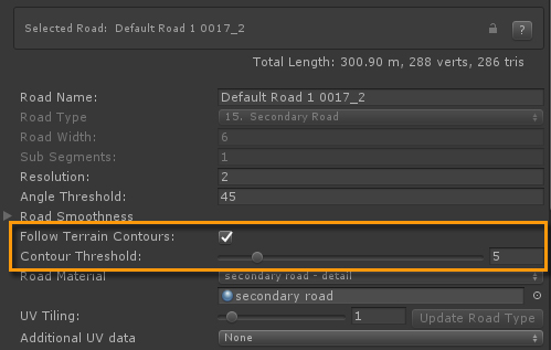
So "Follow Terrain Contours" will resample the road shape based on the terrain surface, the strength is set by "Contour Threshold". The lower this value the more the road will adjust to the terrain shape. For narrow mountain roads you want use lower values, for wider primary roads an higher value.
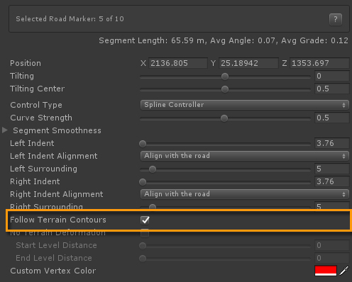
"Follow Terrain Contours" can be switched off for individual markers, for instance in hairpins or areas where you want full control over the road shape and have the terrain adjust accordingly.
Shift + click adds markers at the terrain height. For Mountain roads or roads in hilly areas this is one of the more challenging tasks. Often the road is too irregular and having to reposition markers can be time consuming.
"Distribute Y Evenly" will help here. In the above screenshot markers 24 and 32 were selected by holding the Shift key. When more then one marker is selected, marker alignment options will be visible in the Inspector.
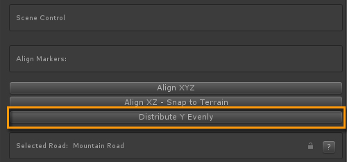
"Distribute Y Evenly" will adjust the height of all markers between the two selected markers resulting in a smooth road. You can manually reposition some markers afterwards in any direction to fine tune the shape, add some noise.
Another example of this is the bridge segment on the Motorway 1 segment, between the markers 21 and 27. Additionally to this, sometimes there can be a significant distance between markers you want to select. In that case you can temporarily increase the marker display distance and handle size in General Settings > Scene Settings
"Distribute Y Evenly" is also useful for river objects.
Marker Tilting or banking is often used to make roads look more realistic, especially for race tracks and mountain roads.
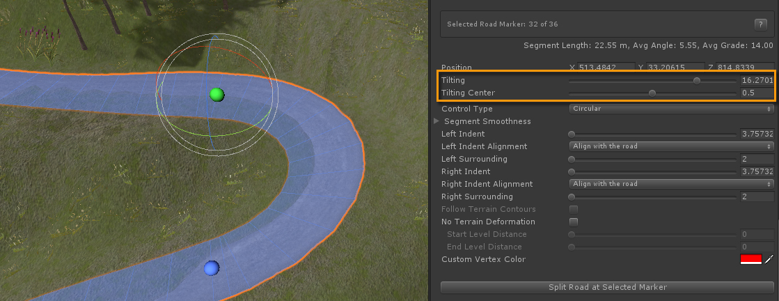
Tilting can be added in the Inspector or in Scene View with the Rotation Gizmo. "Tilting Center" represents the origin of the rotation between the left and right side of the road.
One thing to bear in mind is that higher tilting values will result in this typical sawtooth geometry shape and a less smooth road. It can also have an affect on terrain deformation. Using more Sub Segments will improve this.
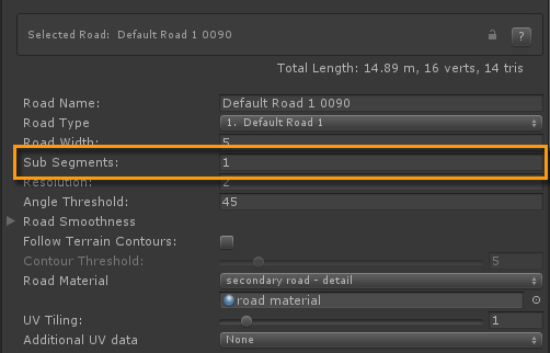
Sub Segments is however currently disabled for roads connected to crossings because crossings do not support this yet. For now you could use an I Connector to deal with this. Use Shift + J to split the road in two roads at the selected marker before you need more sub segments. Do the same near the end where no more sub segments are required. "Sub Segments" is still disabled for the two road sections connected to the crossings, but it is now enabled for the middle road section where you need more sub segments.
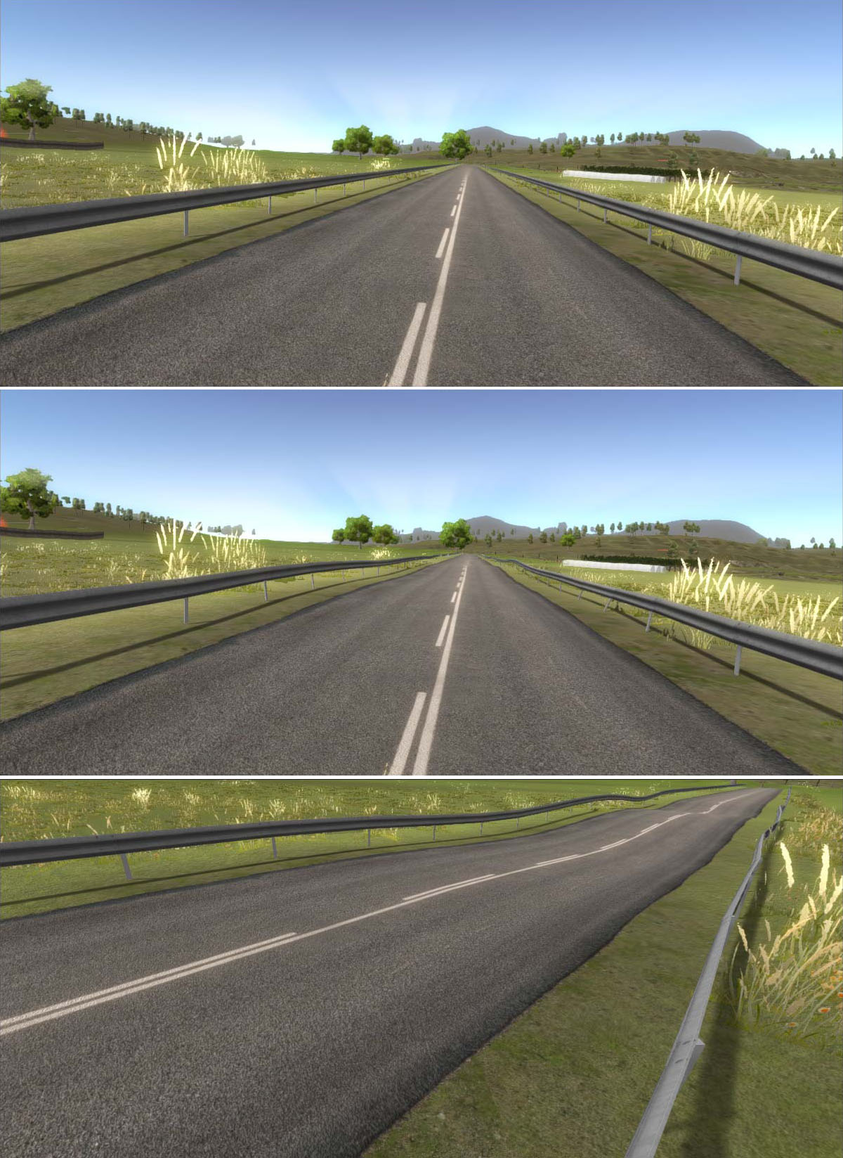
Follow Terrain Contours is a useful way to make roads look more natural, less computer generated. But this will not work on flat terrains. The road smoothness options can help here.
In the above image the first road is standard. The second image has random smoothness/bumpiness. The third image has more bumpiness for one single marker segment.
Road Smoothness can be pre set for road types (General Settings > Road Types) and optionally adjusted for individual road objects.
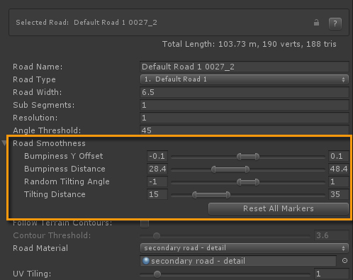
The Bumpiness Y Offset Min Max values represent the random height differences, negative values will push the road downwards.
The Bumpiness Distance Min Max values respresent the random distance over which the bumpiness will take place
For secondary roads and mountain roads you usually want more bumpiness over a shorter distance then for primary and motorway road types.
The Random Titling Angle Min Max values represent the amount of tilting / banking of the road.
The Tilting Distance Min Max values respresent the random distance over which the tilting will take place
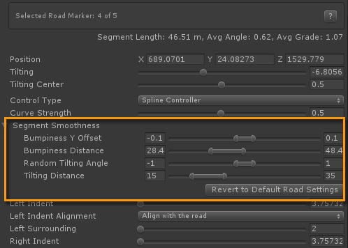
As seen in the 3rd image above, the road smoothness values can be adjusted per marker in the marker section in the Inspector..
One thing to bear in mind here is the grid based nature of the unity terrain object. If the randomness is too strong over short distances the terrains heightmapscale may not be able to handle it resulting in the terrain poking through thwe road or the road floating above the terrain in specific areas.
On a terrain with a standard heightmapscale it is impossible to adjust the terrain to the shape of the track in the below image. This is a shape type of side object (Terrain tab > Bike Track) on top of the terrain, snapping to the terrain on the outer sides. The terrain splatmap map is blended on the side object. The bumpiness / smoothness control works the same on side objects as for roads.
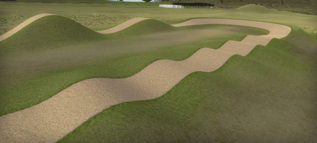
The above screenshot, the Bike track in the demo scene, is created using more extreme road smoothness values per marker.
Marker 1: Both the Min and Max values for Bumpiness Y Offset are set to 2 and both the Min Max distance values to 15. The results are 3 bumps with equal heights covering the same distance.
Marker 5: Here we use 3 for Min and 5 for Max Bumpiness Y Offset. Again we used the same Min Max value for the Bumpiness distance. This results in two bumps over the same distance but with different heights.
Marker 9: Here we used different Min Max values for both. As you can see this has more irregular results,
Markers 13 and 14 are similar to marker 1 but with different values resulting in yet another pattern.
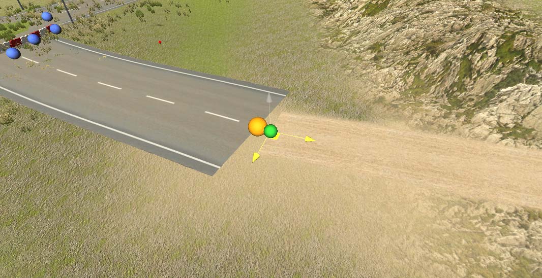
Just like how road markers snap to crossings when within snapping range, starting from v3.1.8 the start / end of a road can be snapped to another road in the Scene View window by dragging a marker to another marker.
Once the dragged marker is close to the start or end of another road and the road types match, that marker will lit up in blue. When the road types do not match the marker will lit up in orange.
After the mouse button is released the two roads will merge into one road object if the road types match. The road will be marked as a Closed Track when the start is snapped to the end of the same road or vice versa.
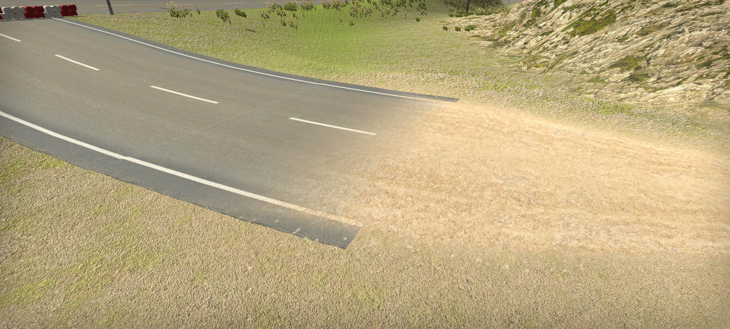
When the road types do not match, the marker handle lits up in orange, the markers will snap as well but in this case an I Connector will be inserted.
The blending between the asphalt and the dirt track was done by selecting the I Connector. In the Inspector a value of 5 was entered for "Connection Distance" for Road 1 and 7 for for Road 2. The "Stretch Width" for Road 2 is set to 2 with "Smooth" selected as the stretch curve. Finally "Blend Textures" is selected as the Transition Type in Additional Settings. This will create a transition mesh with the "primary - sand blend" material assigned. This material uses a shader that will blend the asphalt and dirt textures.

